|
About Applications Casing Setting Directional Drilling Drilling Cost Drilling Hydraulics Drilling Simulator Leak-Off Test Kick Tolerance MPD Simulator Ton Miles Calculator Well Control - Kick Game Well Control Methods iOS Well Control Methods Mac Well Control Simulator Well Control Worksheets Others Knowledge Methods and Concepts Networking Oil & Gas Network
Join to our group "Oil & Gas Systems" on LinkedIn Our Social Profiles: 


Advertisements: 
3D Drill Bit A courtesy of PetroAnimes 
Oil & Gas Links: |
Methods & Concepts
|
|||||||||||||||||||||||||||||||||||||||||||||||||||||||||||||||||||||||||||||||||||||||||||||||||||||||||||||||||

|
See at Youtube: http://youtu.be/20LkKA2ntt8
|
 |
 |
 |
 |
 |
 |
 |
 |
 |
 |
 |
 |
 |
 |
 |
 |
 |
 |
 |
 |
 |
 |

Use our apps to practice this method:
| for iPhone and iPod Touch | for iPad |
 |
 |
|
|


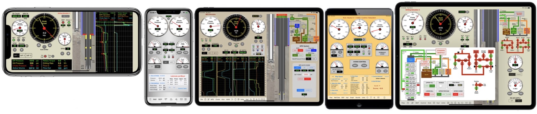
Visit our Portfolio on the App Store for more Oil & Gas apps for iPhone, iPod Touch, iPad and Mac OS X.


Data Files
These slides are for the App "Drilling Simulator 2" but can be used to understand how to work with data files in other apps from our portfolio.


Unit Systems
Select units per Unit System:
METRIC, SI or OILFIELD
or per parameter.
Note about Gravity value used in the hydrostatic
calculations:
Hydrostatic Pressure (Pa)
= Gravity (m/s2) x Density (kg/m3) x Height (m)
This app uses the value Gravity = 9.80665 m/s2
—> Hydrostatic Pressure (Pa)
= 9.80665 x Density (kg/m3) x Height (m)
—> Hydrostatic Pressure (psi)
= 0.051948 x Density (ppg) x Height (ft)


Well Control - Initial Circulating Pressure on deepwater

On deepwater drilling, the subsea bop stack is installed at the well head (on sea bed). In kick condition, the BOP is closed and the flux is deviated to the choke at surface through the choke line. This line has a diameter normally of 3 inches and the frictional pressure losses will increase the pressure at shoe depth. This is a big problem on deepwater wells due to the formation pressure be fragile.
A method to compensate the choke line friction is to decrease the initial choke pressure of this value, monitoring the annulus pressure at the kill pressure gauge instead the choke pressure gauge when bringing the mud pump to slow circulation rate, like on a surface bop well control, and adjusting the choke to set the drill pipe pressure equal to the Initial Circulating Pressure (ICP) calculated by the formula ICP = SIDPP (Shut-in Drill Pipe Pressure) + Pump Pressure @ slow circulating rate when circulating through the drill string with return to the riser.
Some questions:
- Why to use the pump pressure with return to the riser if the circulation of the kick is with return to the choke?
- Why to set the choke fully open during the circulation to record the choke line friction?
- etc.
The answers for these questions are in the calculations in the next slides.


Visit our Portfolio on the App Store for more Oil & Gas apps for iPhone, iPod Touch, iPad and Mac OS X.

Visit our website for more Oil & Gas apps for iPhone, iPod Touch, iPad and Mac OS X.

Kick Tolerance as ρKT Concept


Visit our Portfolio on the App Store
for more Oil & Gas apps for iPhone, iPod Touch, iPad and Mac OS X.

Visit our website for more Oil & Gas apps for iPhone, iPod Touch, iPad and Mac OS X.

Kick Tolerance as Max Kick Volume


Visit our Portfolio on the App Store
for more Oil & Gas apps for iPhone, iPod Touch, iPad and Mac OS X.
Visit our website for more Oil & Gas apps for iPhone, iPod Touch, iPad and Mac OS X.
Kick Tolerance as Maximum Kick Volume
on Directional Wells


Mac version updated:
![]()
iPhone and iPad versions – new update optimized for directional wells coming soon:
| iPhone | iPad |
Visit our Portfolio on the App Store
for more Oil & Gas apps for iPhone, iPod Touch, iPad and Mac OS X.
Visit our website for more Oil & Gas apps for iPhone, iPod Touch, iPad and Mac OS X.
Well Control Volumetric Method
on Directional Wells


Our Volumetric Method Apps available on the App Store

| for iPhone, iPod touch and iPad | for Mac (directional support coming soon) |


Use our apps to practice this method:
| for iPhone and iPod Touch | for iPad |
|
|
|
|
|
Visit our Portfolio on the App Store
for more Oil & Gas apps for iPhone, iPod Touch, iPad and Mac OS X.
Visit our website for more Oil & Gas apps for iPhone, iPod Touch, iPad and Mac OS X.
|
Wait and Weight method on Directional Wells

During drilling operations on oil wells, there may to occur the inflow of formation fluids into the well, which is an undesirable condition. The driller should detect such events and shut-in the well immediately and to record informations corresponding to stabilization of pressures SIDPP (Shut-in Drillpipe Pressure) and SICP (Shut-in Casing Pressure) and the volume gain.
There are two methods more used to well control when the drill string (drill bit) is in the bottom of borehole (normally on drilling when reaches a formation with pressure bigger relative to the bottom hole pressure): The Driller's Method and the Wait and Weight Method (also named Engineer 's Method).
The Driller's Method is performed with two circulations. The first circulation with the original fluid to circulate the influx out of well and the second circulation to fill the borehole with a new fluid. This method can be started immediately after shut-in the well.
The Wait and Weight Method is performed just with a single circulation with the new fluid, but is necessary to wait a lag time until to prepare the new fluid to start the method.
The choice of the method
The choice between these two methods is a controversial question among professionals of oil & gas, but if the rig has already the new fluid available to control the well (the hydrostatic pressure of the new fluid is equivalent to the formation pressure), the Wait and Weight method is aplied and the control will be just with a single circulation in two steps:
Wait and Weight Method
Step 1
Replacing the original fluid in the drill string with the new fluid circulating until the drill bit. Start pump and bring the pump speed until the slow circulation rate, keeping the circulating pressure according the table "Pressure versus Pumped Strokes", starting with the Initial Circulating Pressure (ICP) and ending with the Final Circulating Pressure (FCP).
ICP = SIDPP + Circulating Pressure @ Slow Circulating Rate (recorded previously).
FCP = Pressure(@ scr) x New Fluid Density / Original Fluid Density
Vertical Wells
On vertical section, the rate "pressure drop / stroke" is constant and the calculations can be made in 10 steps.


Directional Wells
On deviated section, starting on Kick-Off Point (KOP), the rate "pressure drop / stroke" is not constant. The calculations will consider the steps by 100 strokes each.


Step 2
Continue the circulation with the new fluid to fill the all annular until the surface keeping the circulating pressure constant equal to FCP - Final Circulating Pressure.
Operational Limits
It is very important to monitor operational limits during the circulation to avoid fracture of the formation, usually at the shoe depth of the last casing.
The advantage of the "Wait and Weight" method is to provide a lower resultant pressure at the shoe depth before the gas reaches the shoe depth, that is, when the new fluid passes through the drill bit, increasing the hydrostatic pressure in the annulus before of the gas to reach the shoe depth.

Conclusion
The Wait and Weight method is advantageous when the rig has already the new fluid available to immediate circulation. Normally the new fluid need a lag time to be prepared. (1) On well closed, an influx of gas is moving up continuously and pressurizing the borehole all the time. (2) The calculations to control directional wells are relatively complex.
If it is not possible for the new fluid to reach the annulus before the gas reaches the shoe depth, due to (1) the lag time to prepare the new fluid or (2) the volume of the drill string is greater than the volume of the annulus above the gas until the shoe depth or (3) the difficulty to calculations on directional wells or (4) formations with low fracture pressure on deepwater for example, it is recommended choose the "Driller's Method" to start immediately after the shut-in the well, holding the circulation pressure equal to Initial Circulating Pressure until the circulation of the total volume of the annulus and to replace the fluid only in the second circulation of this method.
I hope that this simple explanation about the Wait and Wait method on directional wells helps on choicing the method most efficient.
| Well Control Methods apps: | |||||||
|
|||||||
| Well Control Worksheets apps: | ||||||
|
||||||
Use our apps to practice this method:
| for iPhone and iPod Touch | for iPad |
|
|
|
|
Visit our Portfolio on the App Store
for more Oil & Gas apps for iPhone, iPod Touch, iPad and Mac OS X.
Visit our website for more Oil & Gas apps for iPhone, iPod Touch, iPad and Mac OS X.